Prerequisites
This kit is aimed at people who’ve finished the Arduino Starter Kit. It assumes familiarity with the Arduino IDE and basic electronic circuits with buttons and resistors. It is not suitable for absolute beginners.
Gathering materials
To complete this tutorial you need:
- Perspex board
- Arduino nano + USB cable
- LCD screen with I2C backpack
- 4 nuts, spacers and bolts
- 2 push buttons
- 2 resistors (4k7)
- 2 small breadboards
- wires
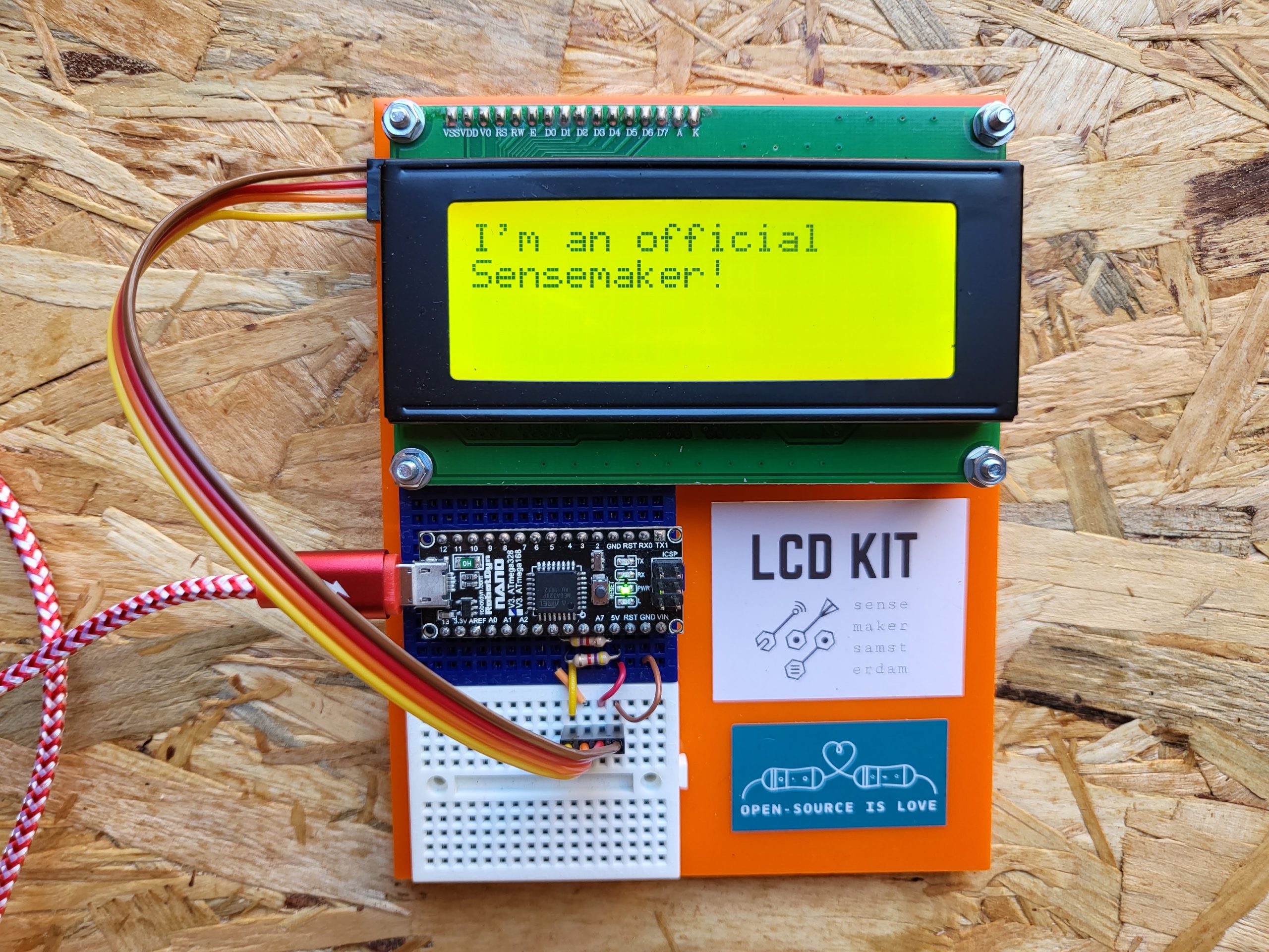
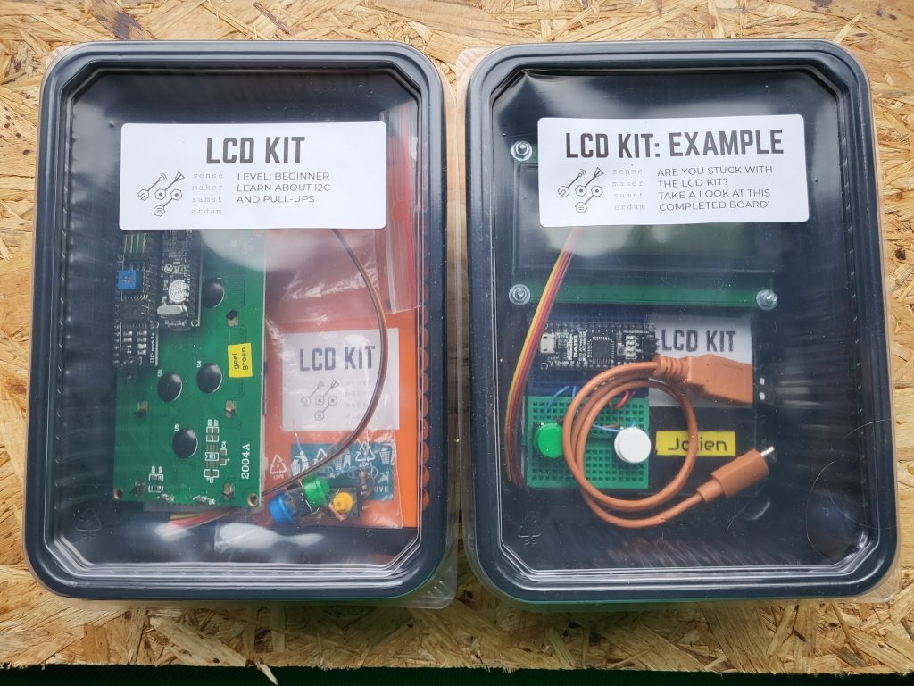
There’s also an example board available which shows the completed kit. Feel free to look at it whenever you’re stuck, but please don’t change anything about it.
Setting up the Arduino IDE
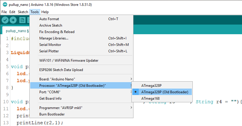
If you haven’t already, install the Arduino IDE. First set the board by clicking Tools > Board > Arduino AVR Boards > Arduino Nano. Secondly change the processor by clicking Tools > Processor > ATmega328P (Old Bootloader).
Preparing the board
Grab the orange plate and the two breadboards from the box. Remove the adhesive tape on the back of the breadboards and stick them left to the stickers onto the orange plate.
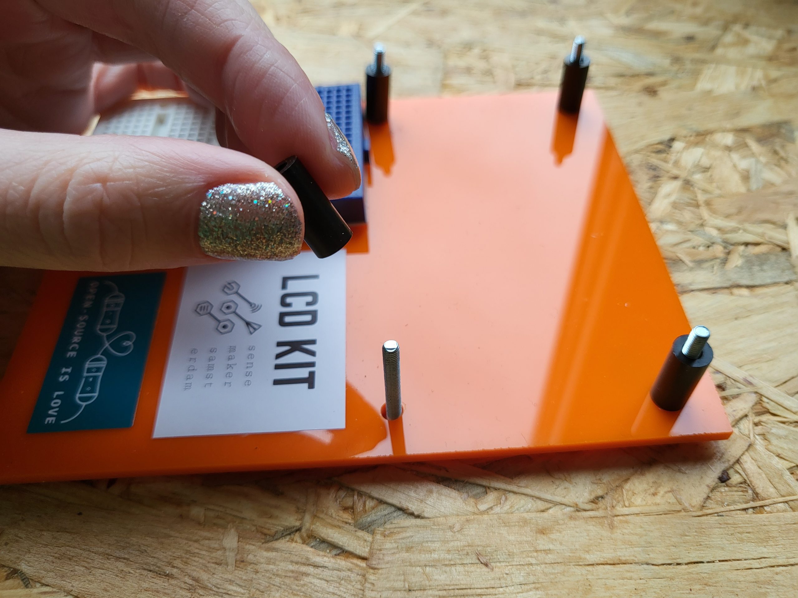
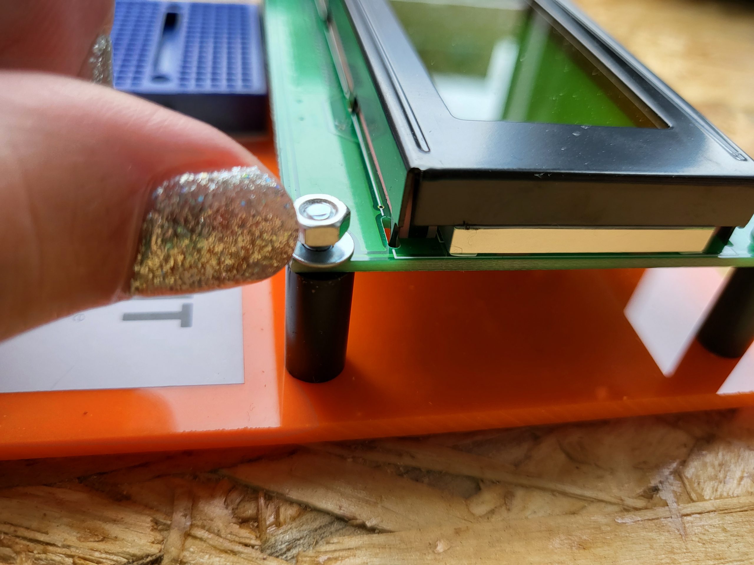
Now remove the LCD screen and the bag with nuts and bolts from the box. Mount the LCD screen on top of the black spacers and finish with the rings and nuts (see pictures).
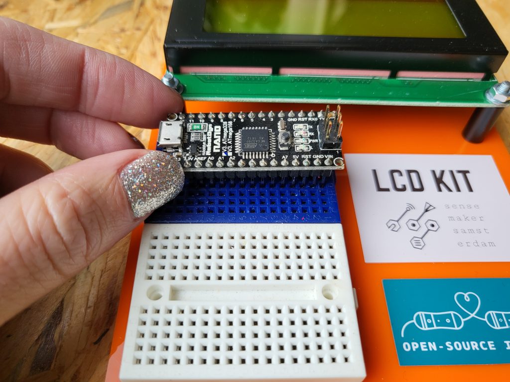
It’s time to add the Arduino! The kit contains an Arduino nano. Place it on the upper breadboard in such a way that the three rows below the Arduino stay free. We need this space later on for placing parts.
I2C
The LCD display has a so-called I2C backpack on its back. I2C stands for inter-integrated circuit-communication which is a protocol invented by Phillips. This protocol needs only two wires besides GND and VCC: SDA (serial data) and CLK (clock). These two lines are called signal lines. When a signal line is connected to GND it represents a 0 (low) and when it is connected to VCC it represents a 1 (high).
In the picture below we see that the pins of the display from the top to the bottom are GND, VCC, SDA and SCL. Connect the female header of the 4-wire-connector to the backpack and make sure that the brown wire is on top. This implies that the VCC = red, SDA = orange and SCL = yellow.
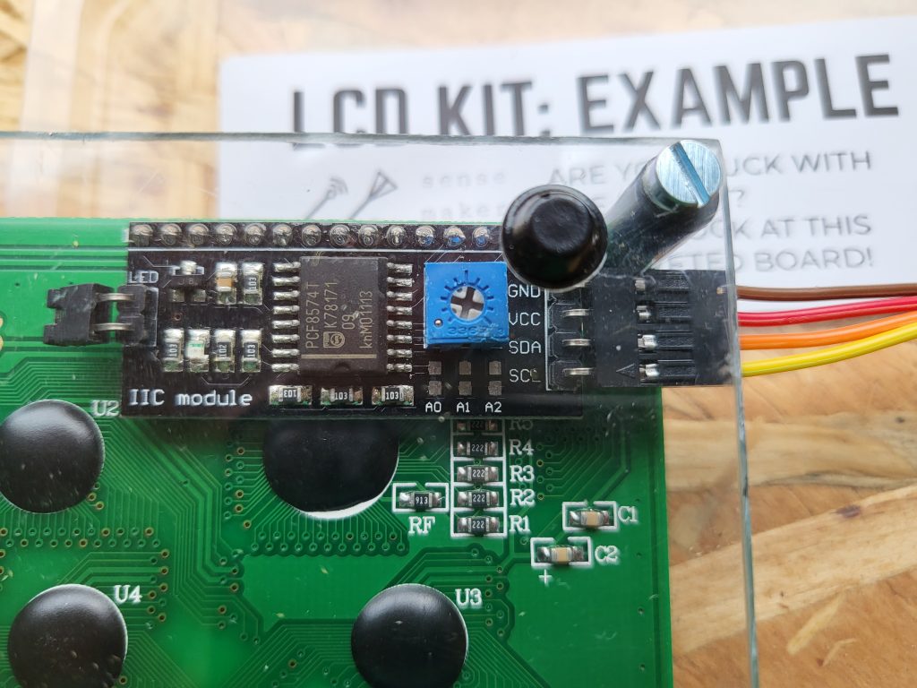
The controller (Arduino) generates a clock signal and sends it to the periphal (LCD screen). The data signal can travel both directions. One of the most useful features of I2C is that several periphals can be connected to the same controller. Each periphal needs its own address to where the message from the controller is sent. The standard address for LCD screens is 0x27.
If you look at the picture more closely, you can see six pads below the blue potentiometer marked A0, A1 and A2. By shorting these pads the address of the screen can be changed. You can use this whenever you want to connect several displays to one controller.
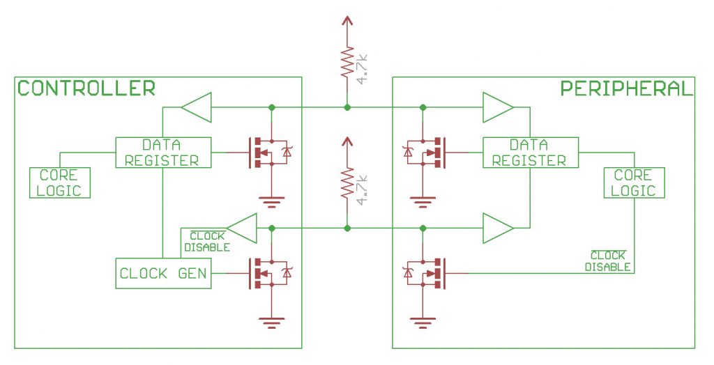
By design, I2C drivers will never pull a SDA or SCL signal to VCC. This construction is called an open collector. This prevents short-circuiting: if the controller would pull the data line to VCC and the periphal would pull it to GND at the same time it could damage components. Therefore there are two options: the line is either disconnected or pulled to GND.
Since we want unused lines to restore to a high signal we connect a resistor from each line to VCC. This is called a pull-up and it ensures the voltage level remains high when it is unused. Can you identify the pull-ups in the diagram below?
Challenge: connect the display
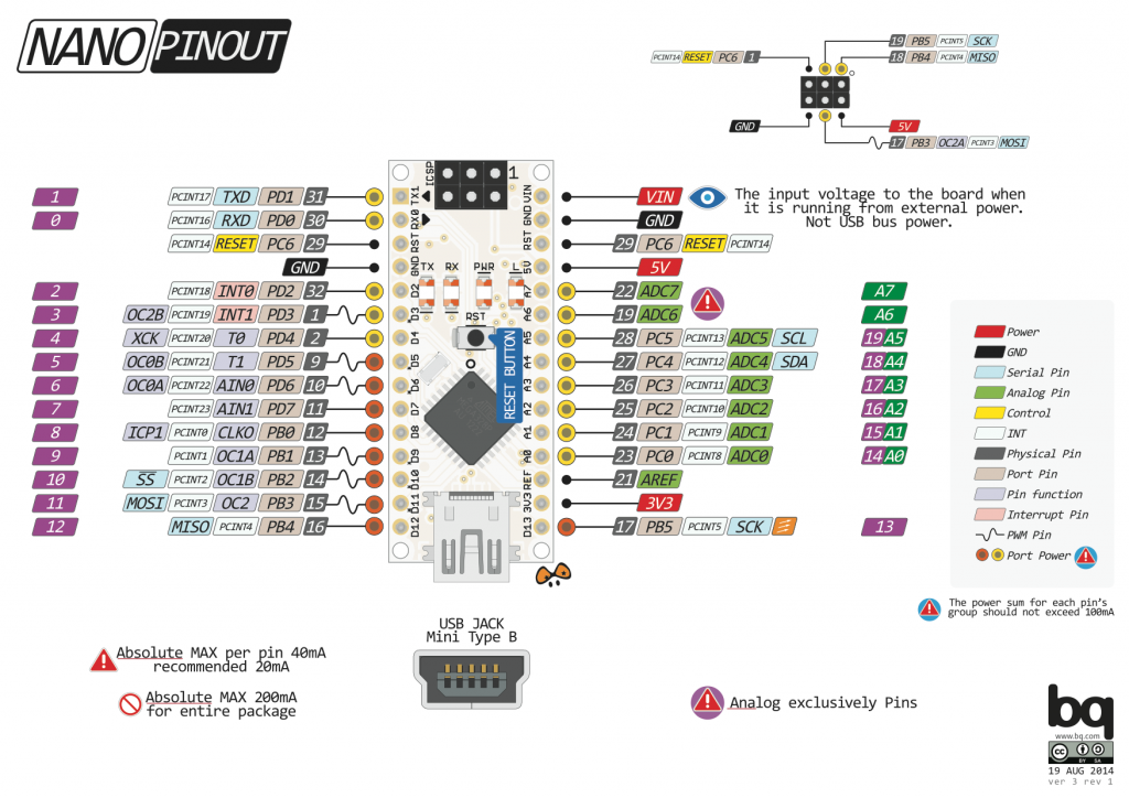
Below you can find the pinout diagram of the Arduino nano. Can you see which two pins can be used for I2C?
First add the 4k7 resistors to pull up the I2C lines.
Connect the LCD screen to the Arduino. Remember we had VCC = red, GND = brown, SDA = orange and SCL = yellow. Since the four wires of the screen are stuck together you have to use the second breadboard in order to plug it in.
Ready? Connect the USB cable to the computer and watch whether a message appears on the LCD screen. If not, check your circuit.
Solution
The pinout shows that pin A4 should be connected to SDA and pin A5 to SCL. The picture below shows a possible solution. Make sure you don’t forget the resistors!

Adding a button
Hook up a button by copying the following setup:
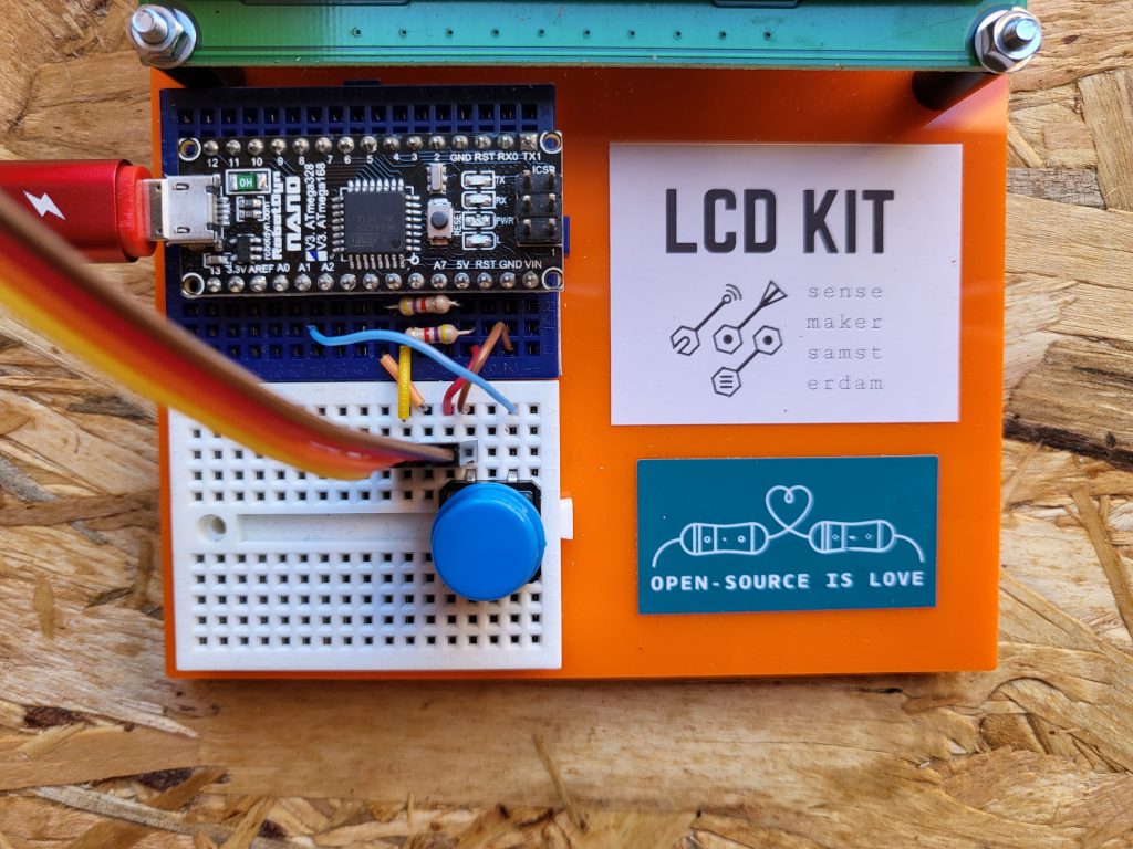
As you can see, the right side of the button is connected to A1, whereas the left side of the button is connected to the ground. This means that the blue wire is either disconnected or equal to GND. Does this ring a bell? We will add a pull-up resistor to make sure we detect 5V whenever the button is not pressed. This is extremely easy to do: Arduino has internal pull-up resistors which you can turn on in the software. It can be activated with pinMode(A1, INPUT_PULLUP); in the setup().
For beginners it might be confusing that A1 reads HIGH whenever the button is not pressed and LOW when it is pressed. However, this is an excellent way to connect a button since you only need two wires and no (external) resistors.
But why didn’t we use this nice feature before with the I2C lines? The reason is that the value of the internal resistor is not correct: it’s too large and it might not stabilize the lines enough.
Creating a random message box
Do you remember the Crystal Ball project from the Arduino Starter Kit? Its code can be found in de IDE by clicking File > Examples > 10. StarterKit_BasicKit > p11_CrystalBall.
Write a new Arduino sketch that shows a random message whenever the button is pressed. If you want to you can use the code below as a blueprint, but feel free to start from scratch.
#include <LiquidCrystal_I2C.h>

#define LCDWidth 20
#define LCDHeight 4
LiquidCrystal_I2C lcd(0x27, LCDWidth, LCDHeight);

const int switchPin = A1;
int switchState = 0;
int prevSwitchState = 0;

void setup() {
  pinMode(switchPin, INPUT_PULLUP);

  lcd.init();
  lcd.backlight();

  Serial.begin(9600);

  String message[4] = {"Press the button", "for a special","message!",""};
  printText(message);
}

void loop() {
  switchState = digitalRead(switchPin);
  if (switchState != prevSwitchState && switchState == 0) {
    // write your code here

    Serial.println("Button pressed!");
    delay(100);
  }
  prevSwitchState = switchState;
}

void printText(String message[LCDHeight]) {
  lcd.clear();
  for (int i = 0; i < LCDHeight; i++) {
    lcd.setCursor(0, i);
    lcd.print(message[i].substring(0, LCDWidth));
  }
}
In case you’re really stuck you can find the completed code at the end of this tutorial.
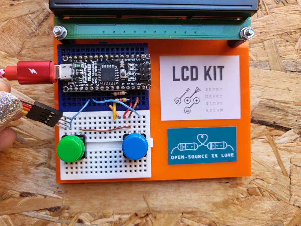
Adding a second button
Add the second button on the left side of the breadboard. Connect one side to GND and the other side to A0.
Creating a tiny digital booklet
Now that we have two buttons, we can create a program that enables users to flip through pages. Add a second button to your previous script by adding
const int switchPin2 = A1;
int switchState2 = 0;
int prevSwitchState2 = 0;
Also set the pinmode of the second pin to INPUT_PULLUP as before. Edit the main loop() by checking whether the second button is pressed and test your code by writing feedback to the Serial port. Debug your code until you can distinguish which button is pressed.
Now add the following global variables:
int pageNumber = 0;
String pages[][4] = {
  {"Hi there,", "I hope you enjoyed", "this LCD kit!", "                   >"},
  {"You're now an I2C", "expert and you know", "how pullups work.", "<                  >"},
  {"See you soon", "at Sensemakers", "Amsterdam!", "<                   "},
};
A page can now be shown with printText(pages[pageNumber]);. Add this line to the setup() to show the first page whenever the Arduino boots.
Edit the loop() such that the left button flips back the page and the right button flips the page over.
What happens if you press left at the first page or right at the last page? Make sure you stay on the same page in those cases. You can take a look at the completed code at the end of this tutorial if you’re stuck.
Done? Congratulations! What are you going to make next?
Follow-up ideas
- In the Sensemakers boxes there are lots of different sensors, such as temperature sensors, humidity sensors, microphones, light sensors and many more. Pick one and connect it to your nano. Can you read its value and show it on the screen?
- Can you create a small reaction time game?
- Connect a second LCD screen to experiment with I2C addresses.
- Riddle: a friend of mine always adds a 1k resistor between the button and GND. Why?
Completed code: random message box
#include <LiquidCrystal_I2C.h>

#define LCDWidth 20
#define LCDHeight 4
LiquidCrystal_I2C lcd(0x27, LCDWidth, LCDHeight);

const int switchPin = A1;
int switchState = 0;
int prevSwitchState = 0;

void setup() {
  pinMode(switchPin, INPUT_PULLUP);

  lcd.init();
  lcd.backlight();

  Serial.begin(9600);

  String message[4] = {"Press the button", "for a special","message!",""};
  printText(message);
}

void loop() {
  switchState = digitalRead(switchPin);
  if (switchState != prevSwitchState && switchState == 0) {
    // write your code here

    Serial.println("Button pressed!");
    delay(100);
  }
  prevSwitchState = switchState;
}

void printText(String message[LCDHeight]) {
  lcd.clear();
  for (int i = 0; i < LCDHeight; i++) {
    lcd.setCursor(0, i);
    lcd.print(message[i].substring(0, LCDWidth));
  }
}

String randomMessages[][4] = {
  {"Welcome to", "Sensemakers", "Amsterdam", ""},
  {"I'm an Arduino Nano!", "", "", ""}
};

void showRandomMessage() {
  int i = random(2);
  printText(randomMessages[i]);
}
Completed code: booklet
#include <LiquidCrystal_I2C.h>

#define LCDWidth 20
#define LCDHeight 4
LiquidCrystal_I2C lcd(0x27, LCDWidth, LCDHeight);

const int switchPin1 = A0;
int switchState1 = 0;
int prevSwitchState1 = 0;

const int switchPin2 = A1;
int switchState2 = 0;
int prevSwitchState2 = 0;

int pageNumber = 0;
String pages[][4] = {
  {"Hi there,", "I hope you enjoyed", "this LCD kit!", "                   >"},
  {"You're now an I2C", "expert and you know", "how pullups work.", "<                  >"},
  {"See you soon", "at Sensemakers", "Amsterdam!", "<                   "},
};

void setup() {
  pinMode(switchPin1, INPUT_PULLUP);
  pinMode(switchPin2, INPUT_PULLUP);

  lcd.init();
  lcd.backlight();

  Serial.begin(9600);

  printText(pages[pageNumber]);
}

void loop() {
  switchState1 = digitalRead(switchPin1);
  switchState2 = digitalRead(switchPin2);

  if (switchState1 != prevSwitchState1 && switchState1 == 0) {
    flipPageBack();
    delay(100);
  }

  if (switchState2 != prevSwitchState2 && switchState2 == 0) {
    flipPage();
    delay(100);
  }

  prevSwitchState1 = switchState1;
  prevSwitchState2 = switchState2;
}

void printText(String message[LCDHeight]) {
  lcd.clear();
  for (int i = 0; i < LCDHeight; i++) {
    lcd.setCursor(0, i);
    lcd.print(message[i].substring(0, LCDWidth));
  }
}

void flipPage() {
  pageNumber = min(2, pageNumber + 1);
  printText(pages[pageNumber]);
}

void flipPageBack() {
  pageNumber = max(0, pageNumber - 1);
  printText(pages[pageNumber]);
}