
In this tutorial you will learn how to program a binary clock that synchronizes itself over the internet.
Gathering materials
For this tutorial you will need the following:
- A computer for programming
- The Sensemakers binary clock board
Setting up the Arduino IDE
If you haven’t already, first install the Arduino IDE. To program the ESP32 with the Arduino IDE we have to add it to the list of available boards using the Board Manager. You can find instructions to do so here. Click Tools > Boards > ESP32 boards and select “ESP32 Dev Module”.
Connecting to a WiFi network
Our clock will retrieve the current time from the internet. To connect the ESP to your router you need the network credentials, i.e. your WiFi network name and its password. If you’re following this tutorial at one of our DIY lab evenings at the library, you can look up these credentials on the whiteboard. Fill in these details at line 3 and 4 of the following sketch and upload it to the board.
#include <WiFi.h>

const char* WIFI_SSID     = "REPLACE_THIS_BY_YOUR_OWN_WIFI_NETWORK";
const char* WIFI_PASSWORD = "REPLACE_THIS_BY_YOUR_OWN_PASSWORD";

void setup() {
  Serial.begin(9600);
  connectToWifi(WIFI_SSID, WIFI_PASSWORD);
}

void loop() {
}

void connectToWifi(char const* ssid, char const* password){
  WiFi.begin(ssid, password);
  Serial.println("Connecting to " + (String)ssid);

  int i = 0;
  while (WiFi.status() != WL_CONNECTED) {
    delay(1000);
    Serial.print(++i); Serial.print(' ');
  }
  Serial.println("Connection established!");
  Serial.println("IP address:\t");
  Serial.println(WiFi.localIP());
}
If you’ve already made the lamp from the WEMOS IOT Kit the code above will look extremely familiar. The library WiFi replaces the WiFi8266 library previously used, but the rest is identical.
Adding time synchronisation
We want to synchronize the time of our clock with an external source on the internet to make sure we always show the correct time. The communication protocol we will use for that is the Network Time Protocol (NTP). The library Time we will use hides the technical details of this protocol and enables users to synchronise with external clocks (time servers) easily.
We will use the public time server pool at pool.ntp.org, which gives access to a random time server. If you’re in the Netherlands at the moment, the retrieved time from the pool will be incorrect. The NTP server sends the Coordinated Universal Time (UTC), whereas the Netherlands observes Central European Time (CET) and Central European Summer Time (CEST). This means that we should add 1 hour to the retrieved time in the summer and 2 hours in the winter. Fortunately these corrections can be done with Time!
Add #include "time.h" to the top of the script to include the Time library and add these four global variables as well:
const char* NTPServer = "pool.ntp.org";
const long GMTOffset = 3600; // seconds
const int daylightSavingTimeOffset = 3600; // seconds
struct tm timeinfo;
To configure the time add
configTime(GMTOffset, daylightSavingTimeOffset, NTPServer); to the setup(), right after connectToWifi(). Now replace the empty main loop() by the following snippet:
void loop() {
  delay(1000);
  if(!getLocalTime(&timeinfo)){
    Serial.println("Failed to obtain time");
  } else {
    Serial.println(&timeinfo, "%H:%M:%S");
  }
}
Do you see a time update every second? Congratulations! If not, debug your code before continuing. Good luck and feel free to ask for help! 💪
The clock’s design
We will use 11 LEDs for this project: 5 to display the hours (16, 8, 4, 2, 1) and 6 to display the minutes (32, 16, 8, 4, 2, 1). To see which pins are available as output pins we have to look at the pinout diagram of the ESP32. A quick Google search for “ESP32 pinout” gives us the following diagram:
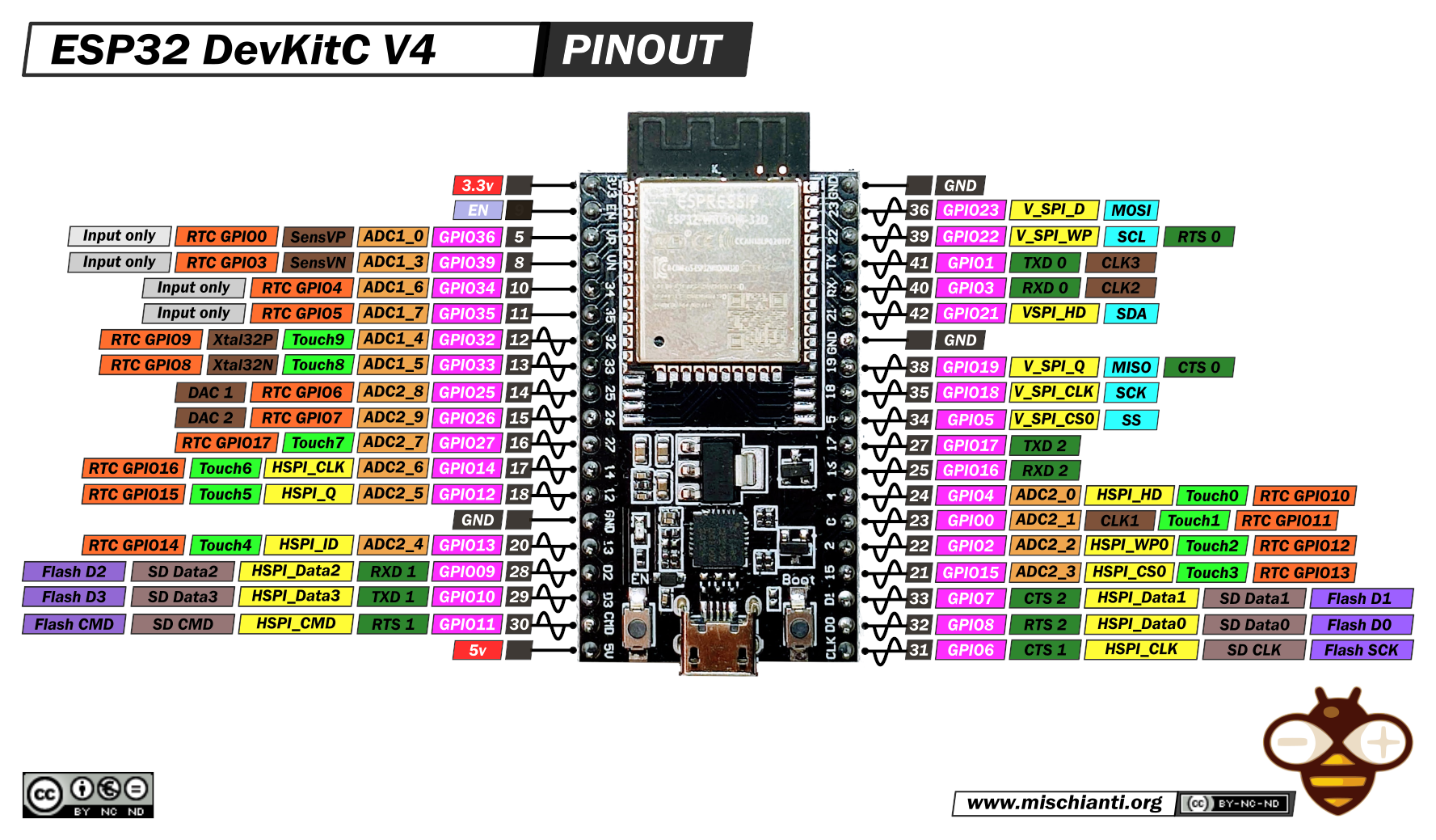
The pinout diagram shows that the four upper left GPIO pins (GPIO 36, 39, 34, 35) cannot be used as output pins. Therefore we will use the six GPIO pins underneath those for the minute LEDs: GPIO 32, 33, 25, 26, 27 and 14 .
For simplicity we will use 5 pins on the right side for the hours. I personally recommend to always leave some I2C pins free in case you want to use those later on. The diagram shows that GPIO 22 and GPIO 21 correspond to SCL and SDA respectively and therefore I didn’t consider using these pins as output pins. Instead, let’s use the pins below GND: GPIO 19, 18, 5, 17 and 16.
You can solder your own LEDs in the hardware part of this tutorial, but for now you can use the pink binary clock board from Sensemakers.
Challenge: display the time in binary
Everything is wired and we know the time, so we’re ready to finish our binary clock. Change the code slightly so that each new minute a function displayTime() is called:
int previousMinute = -1;

void loop() {
  delay(1000);
  if(!getLocalTime(&timeinfo)){
    Serial.println("Failed to obtain time");
  } else {
    if(timeinfo.tm_min != previousMinute){
      displayTime(timeinfo.tm_hour, timeinfo.tm_min)
      previousMinute = timeinfo.tm_min;
    }
  }
}

void displayTime(int h, int m) {
  Serial.println((String)h + ":" + (String)m);
  // TODO: light up the LEDs!
}
First upload the script to the ESP and observe the Serial Monitor to understand how it works. Can you finish the code by making displayTime() light up the right LEDs?
Hint: you might want to read a bit about bitwise operators. Don’t use arithmetic operations such as / and %, that’s the beginner’s approach and this is an intermediate project! 😊
Are your LEDs not lighting up at all? Don’t forget to put your GPIO pins to output mode with pinMode(pin number, OUTPUT); in the setup() function.
When you’re done you could compare your solution to mine at the end of this page. Congratulations on completing the software! If you liked this project you definitely should create your own hardware as well and take your clock home.
Completed code
// IOT Binary Clock
// Jolien Oomens
// October 2021

#include <WiFi.h>
#include "time.h"

const char* WIFI_SSID     = "REPLACE_THIS_BY_YOUR_OWN_WIFI_NETWORK";
const char* WIFI_PASSWORD = "REPLACE_THIS_BY_YOUR_OWN_PASSWORD";

const char mleds[] = {32, 33, 25, 26, 27, 14};
const char hleds[] = {19, 18, 5, 17, 16};

const char* NTPServer = "pool.ntp.org";
const long GMTOffset = 3600;
const int daylightSavingTimeOffset = 3600;
struct tm timeinfo;

void setup() {
  for (int i = 0; i < 6; i++) {
    pinMode(mleds[i], OUTPUT);
  }
  for (int i = 0; i < 5; i++) {
    pinMode(hleds[i], OUTPUT);
  }
  Serial.begin(9600);
  connectToWifi(WIFI_SSID, WIFI_PASSWORD);
  configTime(GMTOffset, daylightSavingTimeOffset, NTPServer);
}

int previousMinute = -1;

void loop() {
  if (!getLocalTime(&timeinfo)) {
    Serial.println("Failed to obtain time");
  } else {
    if (timeinfo.tm_min != previousMinute) {
      displayTime(timeinfo.tm_hour, timeinfo.tm_min);
      previousMinute = timeinfo.tm_min;
    }
  }
  delay(1000);
}

void displayTime(int h, int m) {
  for (int i = 0 ; i < 5 ; i++) {
    if (h & (1 << i))
      digitalWrite(hleds[i], HIGH);
    else
      digitalWrite(hleds[i], LOW);
  }
  for (int i = 0 ; i < 6 ; i++) {
    if (m & (1 << i))
      digitalWrite(mleds[i], HIGH);
    else
      digitalWrite(mleds[i], LOW);
  }
}

void connectToWifi(char const* ssid, char const* password) {
  WiFi.begin(ssid, password);
  Serial.println("Connecting to " + (String)ssid);

  int i = 0;
  while (WiFi.status() != WL_CONNECTED) {
    delay(1000);
    Serial.print(++i); Serial.print(' ');
  }
  Serial.println("Connection established!");
  Serial.println("IP address:\t");
  Serial.println(WiFi.localIP());
}